 Before design grounding system for the plant, soil resistivity shall determine first. This value of soil resistant will be an input in designing grounding system later (i.e. substation grounding, engine hall grounding and pump house grounding). To determine the soil resistivity value, there are several steps to be done.
First of all we will discuss a method used to determine the soil resistivity value.
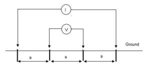
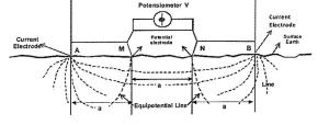
This method known as Wenner four-pin method, developed by Dr. Frank Wenner, US Bureau of Standards in 1915. On these methods used four electrodes, two for current injection and two for voltage measurement. The four electrodes embedded to the ground in straight line, the two outer electrodes are current electrode and two inner electrodes to measure voltage drop due to resistance of soil path when current passed between the outer electrodes.
 Figure 1. Wenner Four Pin Arrangement
The resistance can be measure and resistivity calculated according the following formula.
Where: ρ = Resistivity in Ohm-cm
a = spacing between pin in cm
R = Resistance measurement in Ohm
The depth of electrode shall not exceed the value of a/20
It should be noted that measurement made in this manner indicate average resistivity over a depth of soil corresponding to the spacing between adjacent pin/electrode.
Before perform the test, please take attention to the below condition:
- Prepare the coordinate to be tested.
This coordinate normally located at the equipment (i.e. substation, turbine hall, compressor area and pump house) location. - This test is better to perform in flat location, for 10 meter depth assessment needed 30 meter flat area.
- Cable path shall not crossing any metallic material.
 Figure 2. Wenner Method Work Priciple
The following step used to test the soil resistivity in this method:
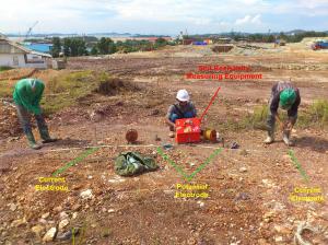
- Placed the soil resistivity measure equipment on the center of the assessment location.
- Put two potential electrode on the left and right side point of view based on the distance test required. This electrode embedded from 5 to 10 cm to ground, based on the soil condition.
- Put two current electrode on the left and right side point of view based on the distance test required. This electrode embedded from 5 to 10 cm to ground based on the soil condition.
- Connect all electrodes cable with the soil resistivity measuring equipment’s.
- Energize the electrode with the power supply form soil resistance measuring equipment’s.
- Please make sure no one touch the electrode when the electrode energize.
- The value of soil resistivity will calculate and appear on the soil resistivity measuring equipment LCD’s or monitor.
Repeat step 2 until step 6 based on the depth required.
 Figure 3. Soil Resistivity Test
Any comment and discussion, please fill the comment field below 😀
Reference:
NEEC – Soil Resistivity


For a Soil Strata we got the ERT values as 656 and 250, so what i can interpret from these?
What do you mean with ERT?
Hi
When doing the Wenner method do you move all 4 pins out at different distances or do you leave the inside pins let’s say a meter from the testing kit and just move the outside pins as far as up to 100 meter if required
Regards
On this method, all pin removed and keep the space to be equal.
what is the relation between the building foundation depth and electrode spacing?
Nice